In this post I’ll describe how I take a sub-$5 Wifi-enabled electrical switch, flash it with open-source firmware, and incorporate it into my home automation. This is a cheap way of being able to turn any small electrical device on and off wirelessly.
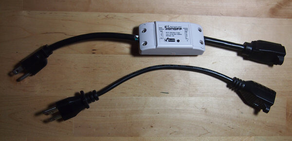
While I could splice the Sonoff directly onto the appliance power cord I’ve found a more versatile approach is to utilize long and short extension cords. I can then reassign the Sonoff if needed and leave the original appliance untouched.
Safety: Sonoff switches are not certified by any US electrical standard. While I feel comfortable using them outside and generally inside as well I would never sandwich one between my wall and couch. Please be safe and smart.
Parts Needed
- Sonoff - wireless electrical switch
- FTDI with cables - to transfer the Espurna firmware to the Sonoff
- Header Pins - to solder onto the board
- USB cable - for the FTDI
- Soldering Iron
- Latest Espurna firmware - I’m using espurna-1.13.5-itead-sonoff-basic.bin
Usage Examples
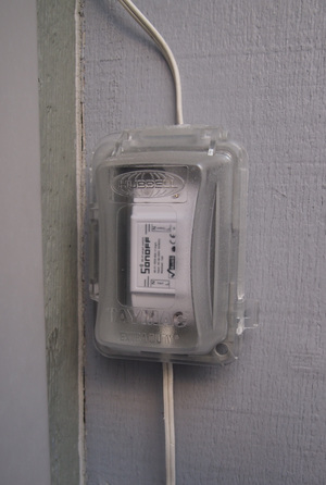
I use one mounted outside in a weatherproof box to control some patio lights.
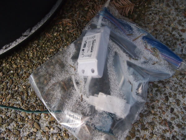
This year I used one to control the Christmas tree lights outside. I thought this one would short out but it survived the winter like this.
Another good use would is to wirelessly control an old coffee pot. Having fresh coffee waiting for me in the morning is one of the few reasons I’m able to get out of bed. The problem is that I don’t always get up at the same time, especially on weekends. The solution is to use the dumbest coffee maker I could find, one without a built-in clock where you flick the big red switch in the front and as soon as there’s power it starts brewing. Leave the switch in the ON position, plug the coffee maker into the cable we’re about to make and use my home automation to trigger the switch to turn on. In my case I have a “Good Morning” button on my automation panel that kicks off a routine, and this is one of them. By the time I make it downstairs coffee is brewing.
Soldering Headers to the board
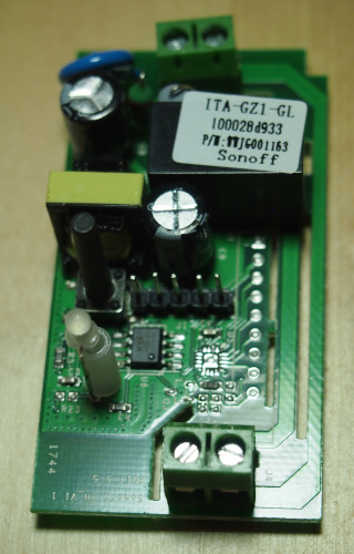
In order to flash a Sonoff you have to be able to interface with it. While the necessary connectors are available, they have no pins connected and so I first need to solder some header pins to the board so I can attach the cables.
The two photos below show the before and after. You can see the 5 new pins in the second photo.
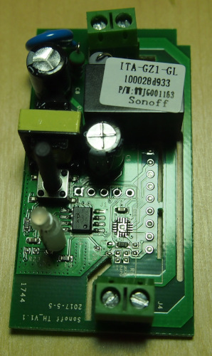
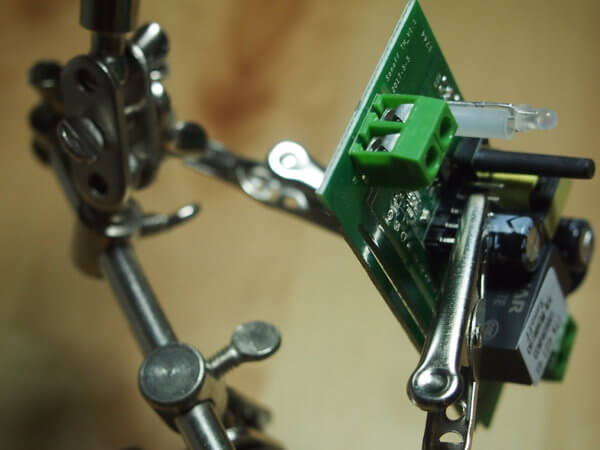
Soldering and holding at the same time is impossible so I use a little helper.
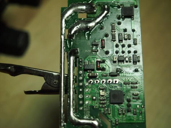
Here you can see the underside of the board with the pins protruding. This is where you apply a little solder to get the pins connected to the board. Once you’re done we’re ready to flash the board with its new software.
Flashing
With the pins in place you can now connect the board to your FTDI.
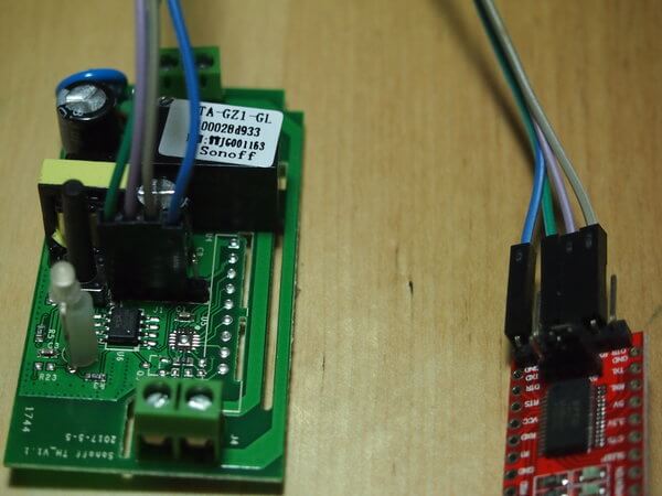
What we’re doing here is connecting 4 cables for power (VCC), ground (GND), transmit (TX), and receive (RX).
The VCC on the FTDI connects to VCC on the Sonoff
The GND on the FTDI connects to GND on the Sonoff
The RX on the FTDI connects to TX on the Sonoff
The TX on the FTDI connects to RX on the Sonoff
Note that the transmit pin on one side connects to the receive pin on the other side.
In the diagram my cables connect to the FTDI as follows:
Blue - GND
Green - VCC
Purple - TX
Grey - RX
On the Sonoff, starting with the leftmost pin, the pinout is:
Pin 1 - VCC
Pin 2 - RX
Pin 3 - TX
Pin 4 - GND
Pin 5 - Empty - GPIO 14
Now that we’re wired-up we can flash.
I typically open a command prompt and get my command ready to run before connecting the Sonoff. The Sonoff should not be connected to any other power source when you do this. It will receive the power it needs through the FTDI.
Further instructions can be found on the Espurna flashing page.
Start by downloading the firmware for your device. I’m using espurna-1.13.5-itead-sonoff-basic.bin
Download and install esptool.
This is usually done with pip install esptool since it’s a command line python tool.
The first command we’ll use is sudo ./esptool.py --port /dev/ttyUSB0 erase_flash so be sure you can run esptool and have the command ready to execute. If you run it without the FTDI connected it will fail because there is no /dev/ttyUSB0 yet.
Note that I’m doing this on an Ubuntu workstation. On a different OS your port will probably be different and will need to be changed in the command to reflect that.
Now, while pushing down on the tall black buttonon the Sonoff, plug the USB cable into your computer. This will place the Sonoff into flashing mode. You won’t know if it’s working until you issue the first command to erase the flash.
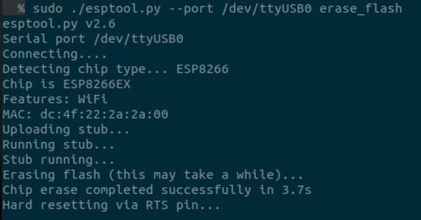
Now run the erase command:
sudo ./esptool.py --port /dev/ttyUSB0 erase_flash
If everything is working you should see the output below immediately.
If the screen shows
Connecting........_____....._____.....
then no communication is occuring.
Check to make sure you connected the cables correctly. TX goes to RX and RX goes to TX.
Check /dev and make sure ttyUSB0 appears when you plug in the FTDI or that you’ve specified this port correctly.
Go back and check and re-solder your pin connections.
After it’s erased and you know you have communication, go ahead and flash the device.
sudo ./esptool.py --port /dev/ttyUSB0 write_flash --flash_size detect --flash_mode dout 0x00000 /home/user/Downloads/espurna-1.13.5-itead-sonoff-basic.bin
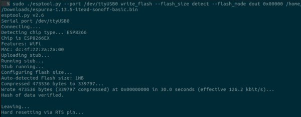
If there’s an issue, unplug the USB cable from your computer, hold down the button on the Sonoff and plug the USB cable back in. Now try flashing again.
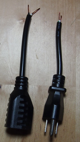
Now take the cord you want to control and cut it where the Sonoff will be placed. Strip away any outer and inner sheath covering the wires.
Be sure to trim the outside sheath back far enough that you can attach the Sonoff cover plates. That’s easier to do now than later.
Note that the Sonoff is marked on the front with one side as “Input” and the other “Output”.
The side of the extension cord with the 3 prongs that plug into the wall connect to the “Input” side.
By convention the color code for electrical cables is as follows:
BLACK = HOT
WHITE = NEUTRAL
GREEN = GROUND
So for us that means we’ll connect the wires like so:
Green gets cut back and taped
White connects to N
Black connects to L
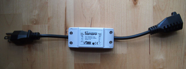
Tighten the screws and apply the cover plate. Congrats, you have a wifi-enabled extension cord!
Connect to Espurna
Plug the cable into an electrical socket. The light on the outside should flash green every second.
Using your computer scan for available wireless networks you should see one named ESPURNA-XXXXXX where the X’s are the last portion of the device’s MAC address.
Connect to this network with a password of fibonacci.
Now open a web browser and navigate to http://192.168.4.1
You’ll immediately be prompted to change the default admin password as shown below.
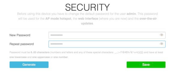
After changing the password turn off your machine’s wireless radio and go into wireless settings. Find the ESPURNA-XXXXXX network name and choose to “forget” the network so the password is erased. Enable Wifi and reconnect to ESPURNA-XXXXXX with your new password. Now navigate to http://192.168.4.1 and when prompted use admin as the username and once again supply your new password.
You should be greeted with the Espurna Status page.
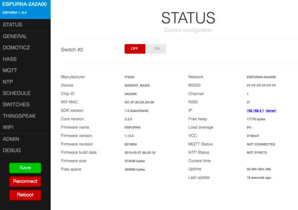
Now go down to Wifi on the left and connect the device to your wireless network by specifying the SSID name and password. Save the setting and reboot the device.
You can now control the switch on your network by navigating to its IP address with a web browser or connecting the Sonoff to your Home Automation system through MQTT.
Reset: If at any point the device becomes unresponsive just hold down the black button on the top for 20 seconds while the device is powered on and it will reset. You can then connect to the ESPURNA-XXXXXX network with the default credentials and start over. This is sometimes necessary after an over-the-air firmware update.